Camera Motion Research & Testing

Research

After creating my abstract cube, I wanted to test a way of linking the camera’s rotation based around the abstract cube, which will be centred within my scene. The aim of this will allow my camera to rotate around the cube whilst having a shallow depth of field focusing on the ring of spheres in front.

I found a video on YouTube which explored this rotation element that I want to introduce into my own work – however the objects used weren’t exactly the same but the basic principles behind it could still be adapted to my project.

Overall, the main element that I took away form this was the use of splines – I didn’t know that I could use a spline to create the camera motion within C4D. Now this I have gained this knowledge, I will have a lot of creative freedom with my camera movements when it comes to rendering the animation. In addition, I felt that the C4D tag ‘Align to Spline’ was very critical within this as without it, the camera wouldn’t have been able to follow the specific shape.

Testing

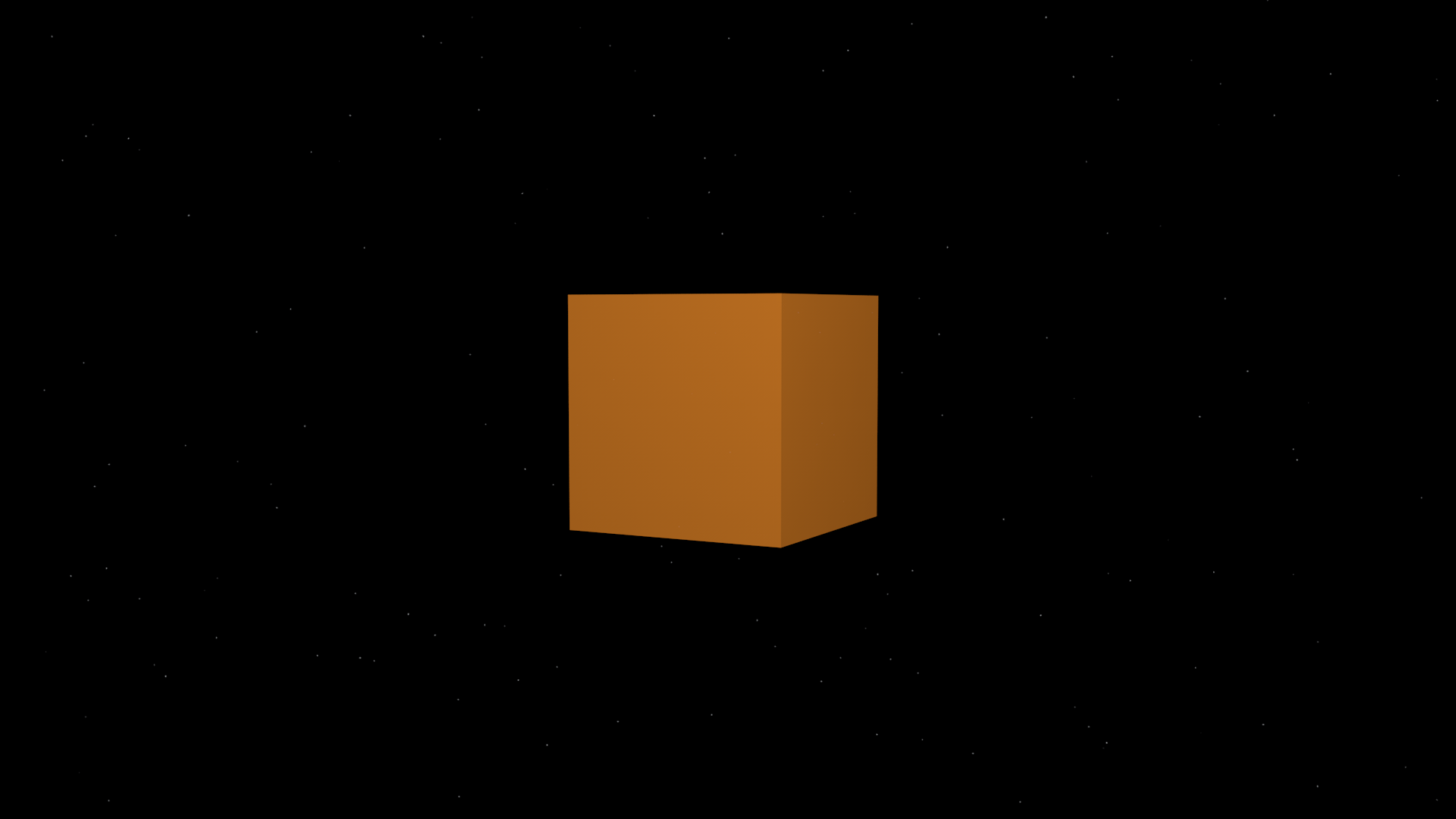
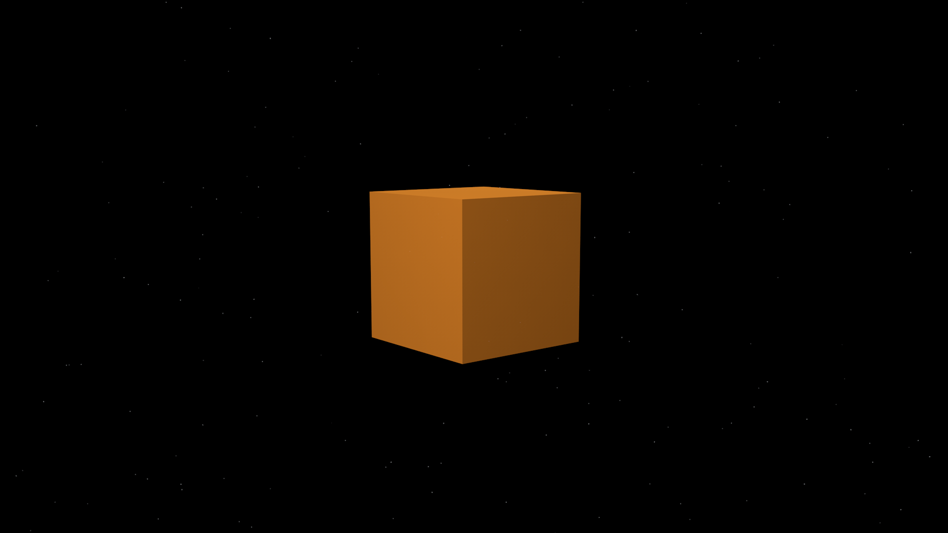
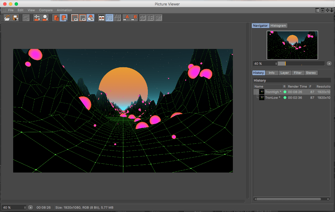
After watching the tutorial, I set up a scene which resembled something similar to my animation with the extra additions of the spline and the camera. I then went about creating some interesting camera movement by altering the camera position within the key frame limit (o-150), which would alter how far around the spline it would travel and, then also by using the rotate tool to change the angle of the spline which the camera followed – by doing this, I created this animation below with interesting textures and an over sized sphere with a ‘Starfield‘ colour texture on it.

Overall, I feel that using the align to spline method of camera movement would be an easy and effective way of creating camera motion within my animation – this particular example, although very exaggerated could be slowed down to create the type of shot that I would like within one of the scene in the animation. The section in mind is scene 2 (which can be seen in the Storyboard) where there is a shallow focus on the spheres floating in front with the cube in the background, however, I would need to change the Spline Position from 100% at the end of the scene to a smaller value like 10% to allow for the camera motion to be slow enough to capture all the details.

When this is done, it will achieve a very aesthetically pleasing shot, which I feel will be good enough to be further edited in After effects with the extra ideas I had in mind.
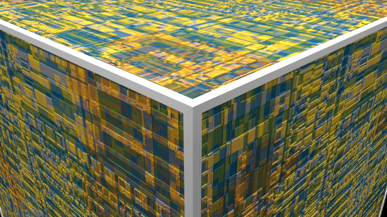
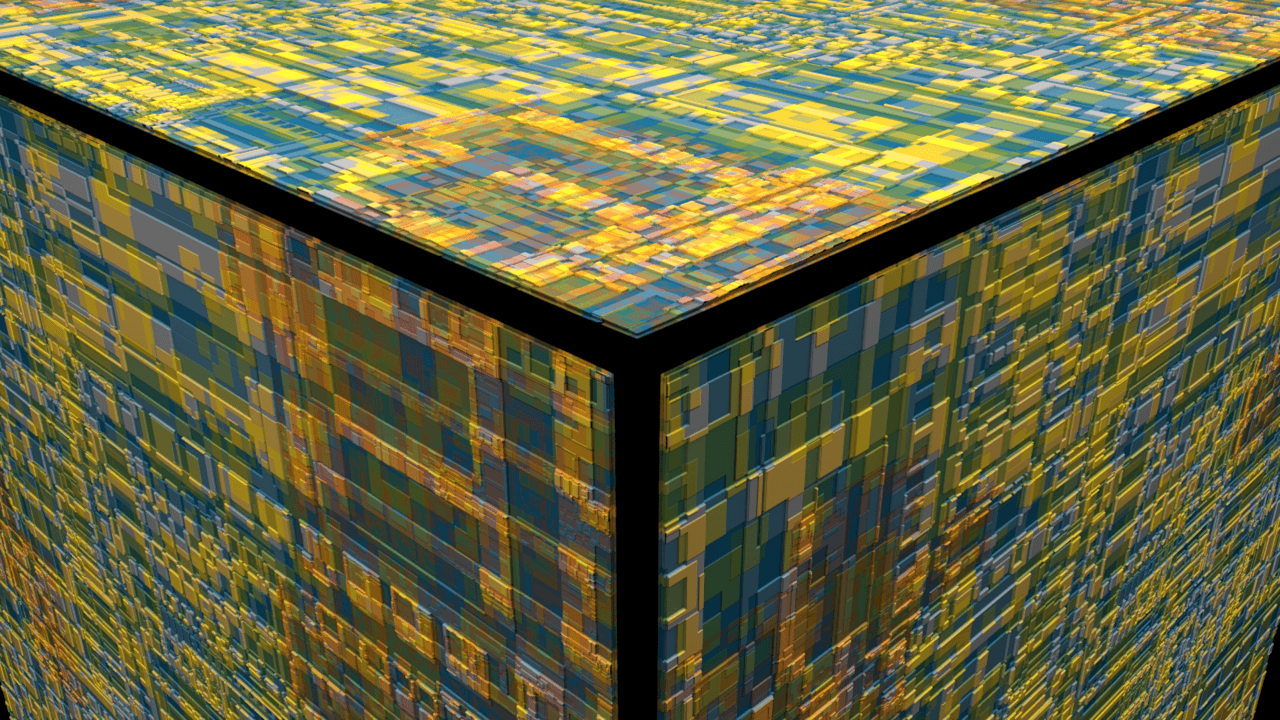
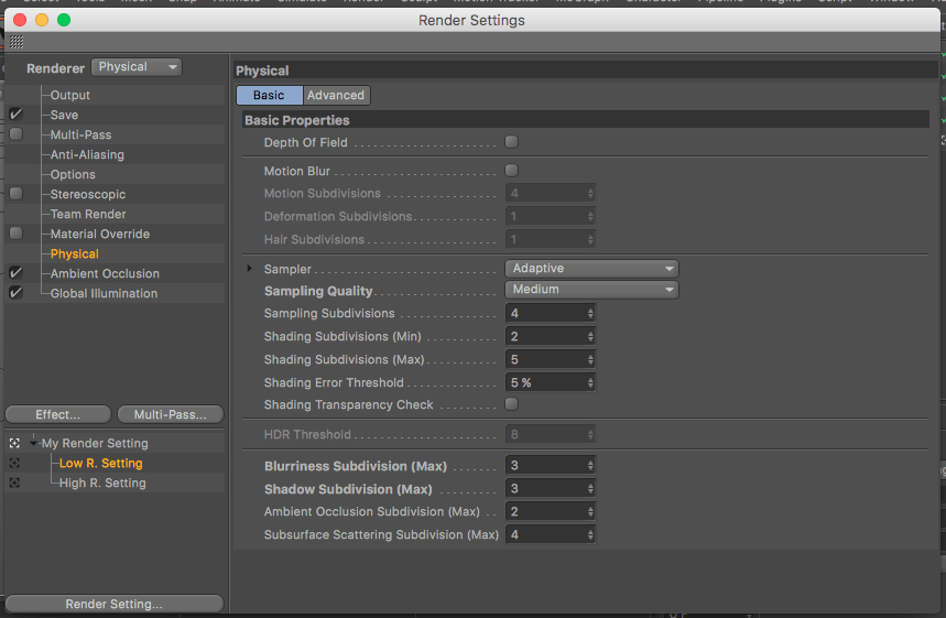
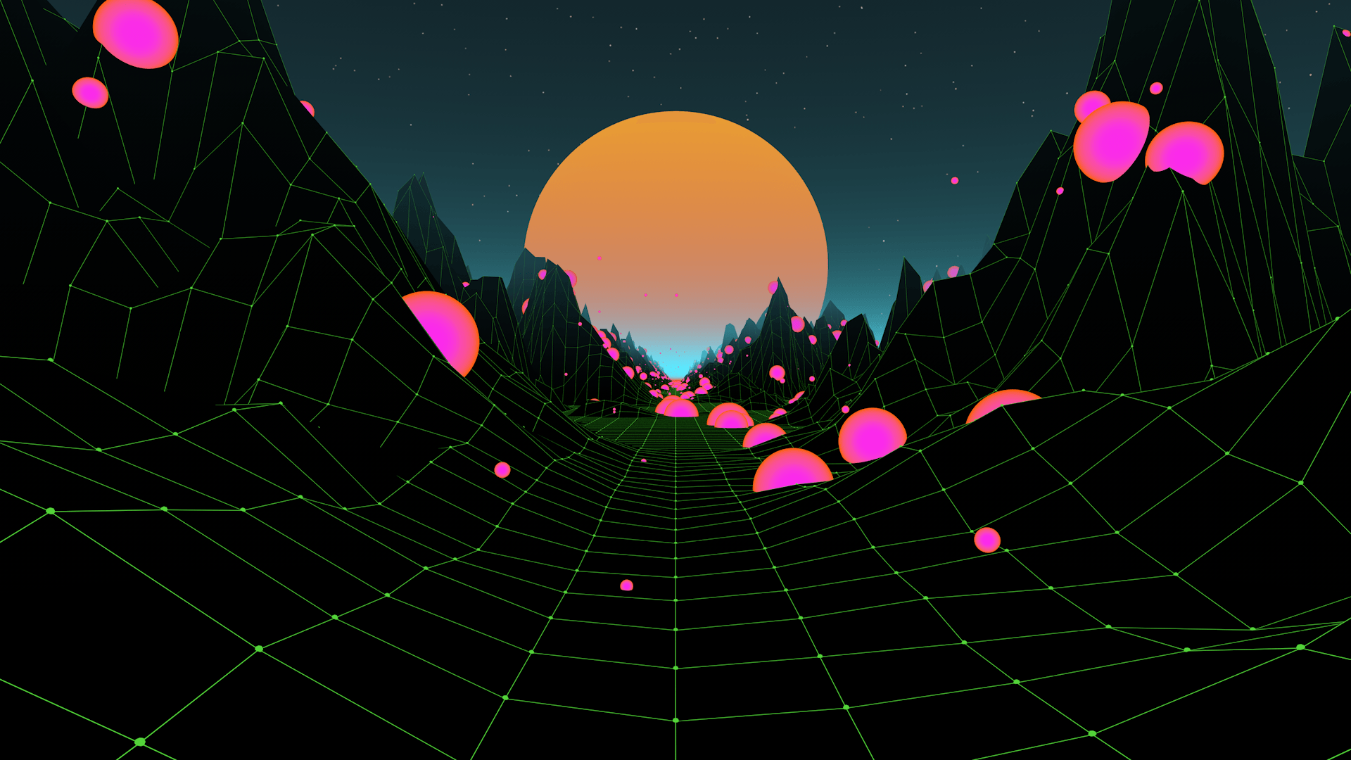
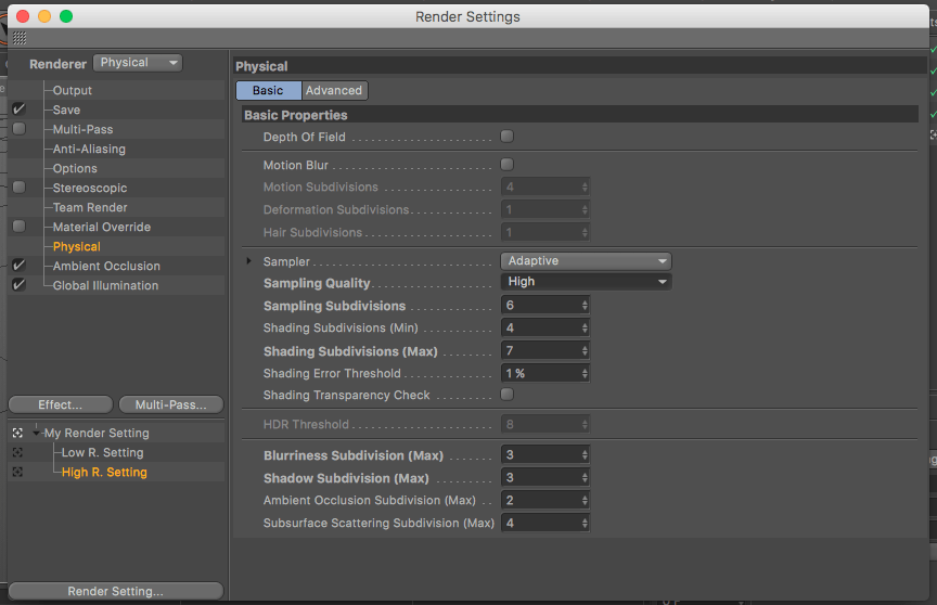
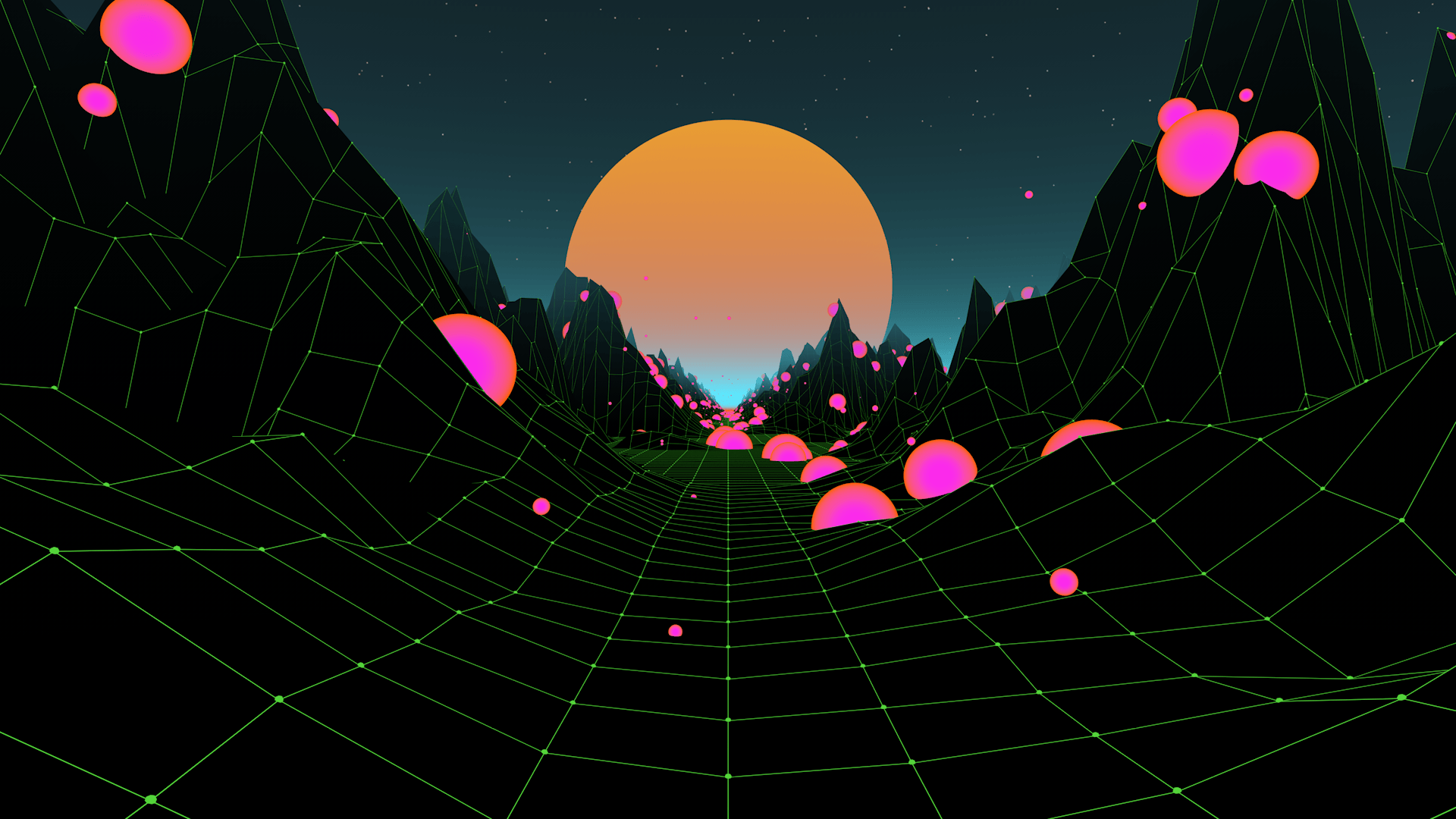
Renders

Untitled 0030

Untitled 0042

Alternative Displacement Map

After encountering and solving problems with my displacement map, I had thought of a different way of getting around it. In my first displacement map creation I created small geometric shapes inside of the artboard – I realised that because I allowed these shapes to touch the very edge, that they would be displaced upwards which would prevent it from connecting perfectly to the vertices when mapped onto the 3D object.

After realising this, I decided to alter my pre-existing displacement map by adding a white or black rectangle to the edge of it – this would then mean all of the vertices would be displaced to the same level, allowing to connect together perfectly on the 3D object.

Firstly, I started in Illustrator because my initial thinking was to start it from scratch, however, I realised that I would be creating more work for myself as I could have just added the boarder in After Effects and exported it straight away saving myself lots of time – which I did.

After exporting, I then created a quick mock up of my scene – adding the displacement channel with the image and also adding the colour, which produced these two renders below:

White boarder

Blackboarder

Overall, the test was successfully as the boarders made the vertices connect up perfectly on the 3D cube which I was hoping it would do. However, I feel that for next time i will have to change the size of the coloured boarders as the one I made is far too big and leaves a lot of untextured space on the cube. Additionally, the colour of the boarder will have to be changed as both the white and black in these renders don’t suit the reset of the aesthetic that is being used.

Displacement Map Solution

After coming across the displacement map problem, I have been searching for different solutions and found myself looking on lots of forums which specialised in Cinema 4D – to which I found someone else who was experiencing a similar problem to myself on the forum website called Otoy.

Screen Shot 2017-11-21 at 01.01.14

Unfortunately, this problem wasn’t resolved and the user actually found a way around the issues with a noise effector inside of C4D as he was trying to create a rough effect to simulate building bricks.

After not being able to find anything useful on the topic that was relevant to me, I went back to the initial tutorial to see if I had missed anything. On the 19 mins 30 secs mark, the tutorial starts to mention about an issue that they were experiencing which was the exact same problem I had – how the displacement map seems disconnected and is described as “coming apart from the seams”. This was then corrected by altering the Mid-Level of the displacement map. However, that is for the Octane Renderer and that feature isn’t available in the stock version of Cinema 4D.

Even though the Mid-Level setting available in the Octane Renderer wouldn’t work for me, I still noticed that the node was connected the overall displacement material so I went an checked my displacement settings but nothing worked. So my next idea was to try an add a deformer, as I knew the object was a cube – I tried adding a bevel deformer to it to see if this would merge the vertices of the displacement map together, which I did but with an interesting effect.

The effect can be seen below in the renders provided, the ‘before’ render shows that the object looked like before the bevel deformer was added to the cube – not how all the displaced shapes rise up quite high and there is a good amount of colour variation which was  achieved through the initial creation process.

Before:

Edgeissue


After the bevel deformer was added, it created an odd effect to the surface of the object by flattening the protrusions from the displacement map – also this result may have decreased the overall effect I was wanting to achieve, it also also solved the edge vertices problem that can be seen in the first render.

After:

Edgesoultuion

Overall, the bevel deformer has eliminated the holes in the displacement map on the vertices but, it has also changed the overall effect of the displacement map as the protrusions are lower in height and seems like the deformer has decreased the overall strength of the map. From a close perspective, I really like the effect the deformer has given the object as it resembles the surface of a space station or technologic material – however, I still need to the view the effect as a whole on the object as it might not look aesthetically pleasing form a distance. To further develop this I will continue to alter the settings of the bevel deformers to see what results they produce, which I will document with renders.

Displacement Map Problem

After successful adding the displacement map to the cube and adjusting the segments & sub-polygons, I noticed small section on the vertices of the cube where the map didn’t join up correctly – this can be more specifically be seen in the render below where square/rectangular holes are visible.

Edgeissue

As I intend to get some close-ups of the cube for the animation, this will need to be fixed. I think that this could either be done within C4D itself through the mapping settings on the material – the way the texture is mapped onto the shape is currently set to UVW Mapping which might have an involvement with the issue. In addition, it could also be done in  Illustrator or After Effects by adding a small white boarder to the edges above all the layers – this would mean that all of the boarders would be at the same displacement level as each colour density represents displacement value. I will research into this further and test any potential solutions.

Render Settings

As my animation is coming towards the final stages of completion, I feel the need to research and test out different render settings in order to speed up my workflow. I often find that I spend a long time waiting for my renders to complete after making small changes which has a detrimental effect on my workflow. The video below gave me some useful times on how to speed rendering up:

Optimising Scenes in Cinema 4D from Luxx on Vimeo.

Overall, the tutorial Optimising Scenes in Cinema 4D focused on two crucial elements: 1) Having low render settings for the development stage of the animation and 2) Having high render settings for the final render when the animation is complete.

Low Render Settings:

Within the tutorial it went through each individual setting, basically turning ever setting down a couple units so that the overall speed of the render is decreased. All of the settings were specific to the physical render engine which I intended to use anyway – the most significant alteration of the renderer was the Sample Quality, as the setting was changed to medium, this drastically changed the values within the setting which was, at first concerning as I thought it would provide enough detail. However, I later found out that this would be more than sufficient enough for development stages of project as it would allow for the render times to drop drastically which would further allow me to make alterations much faster.

Screen Shot 2017-11-16 at 18.31.24

Example render using the low settings:

TronLow

High Render Setting:

After I had used the low render setting to make the desired alterations to the animation, I had to figure out a higher setting for the final render which involved turning everything up. As I was planning on using the physical renderer, I decided to turn the default Sampling Quality setting from medium in the low setting to high – this further bumped up the units to produce more detail and most notably decreased the error threshold to 1%. After conducting a test render, I felt that I could have changed the Sampling Subdivisions up a couple of units more to produce more detail which would be desirable at the cost of a bit extra time, which I feel it is worth.

Screen Shot 2017-11-16 at 18.31.15


Example render using the high settings:

TronHigh

Conclusion

Using the low settings will produced really fast renders which will in turn speed up my workflow as I will be able to make small changes quickly to my animation, however, this speed will come at a sacrifice as the quality wont be as good. Oppositely, using the high settings will produce really high quality renders which will be very beneficial when coming into after effects as it’ll look very aesthetically pleasing, however, this quality will also come at a sacrifice as the time it will take to render each time will be very long. The image below shows two test renders I conducted with the different render settings. Overall, I feel that both images look identical on screen which is very surprising, however, the low render setting took far less time in comparison to the high render setting – approximately 5 mins 10 sec less. The low setting would be far more beneficial for me to use in the development stage of the animation as it will allow for render times to decrease, which in turn will increased my workflow allowing me to change and tweak settings fast. After the development stage has been completed, I can then switch to the high render setting which will give me better detail ready to export to After Effects.

Screen Shot 2017-11-16 at 18.47.54