Displacement Map Solution

After coming across the displacement map problem, I have been searching for different solutions and found myself looking on lots of forums which specialised in Cinema 4D – to which I found someone else who was experiencing a similar problem to myself on the forum website called Otoy.

Screen Shot 2017-11-21 at 01.01.14

Unfortunately, this problem wasn’t resolved and the user actually found a way around the issues with a noise effector inside of C4D as he was trying to create a rough effect to simulate building bricks.

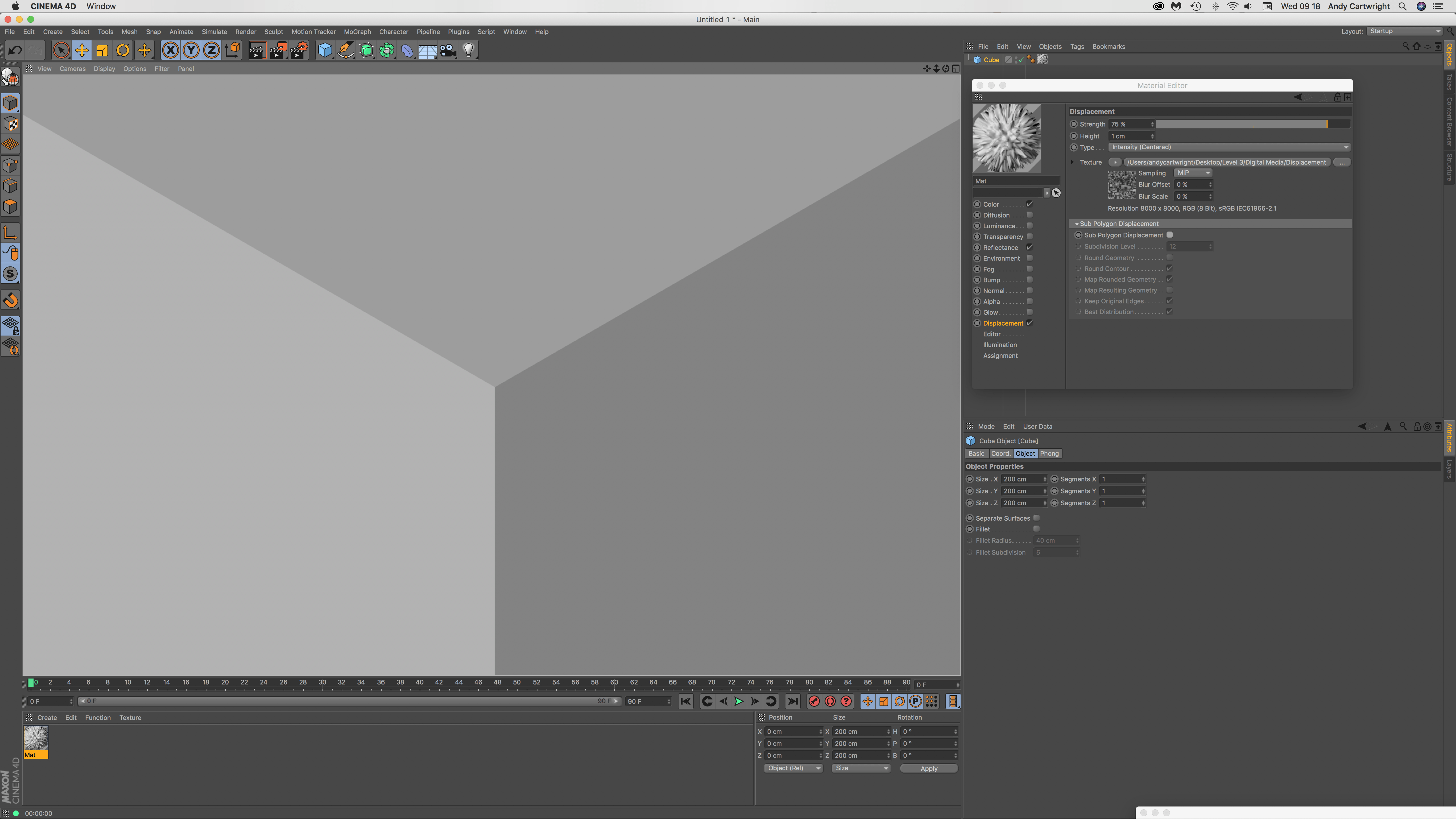
After not being able to find anything useful on the topic that was relevant to me, I went back to the initial tutorial to see if I had missed anything. On the 19 mins 30 secs mark, the tutorial starts to mention about an issue that they were experiencing which was the exact same problem I had – how the displacement map seems disconnected and is described as “coming apart from the seams”. This was then corrected by altering the Mid-Level of the displacement map. However, that is for the Octane Renderer and that feature isn’t available in the stock version of Cinema 4D.

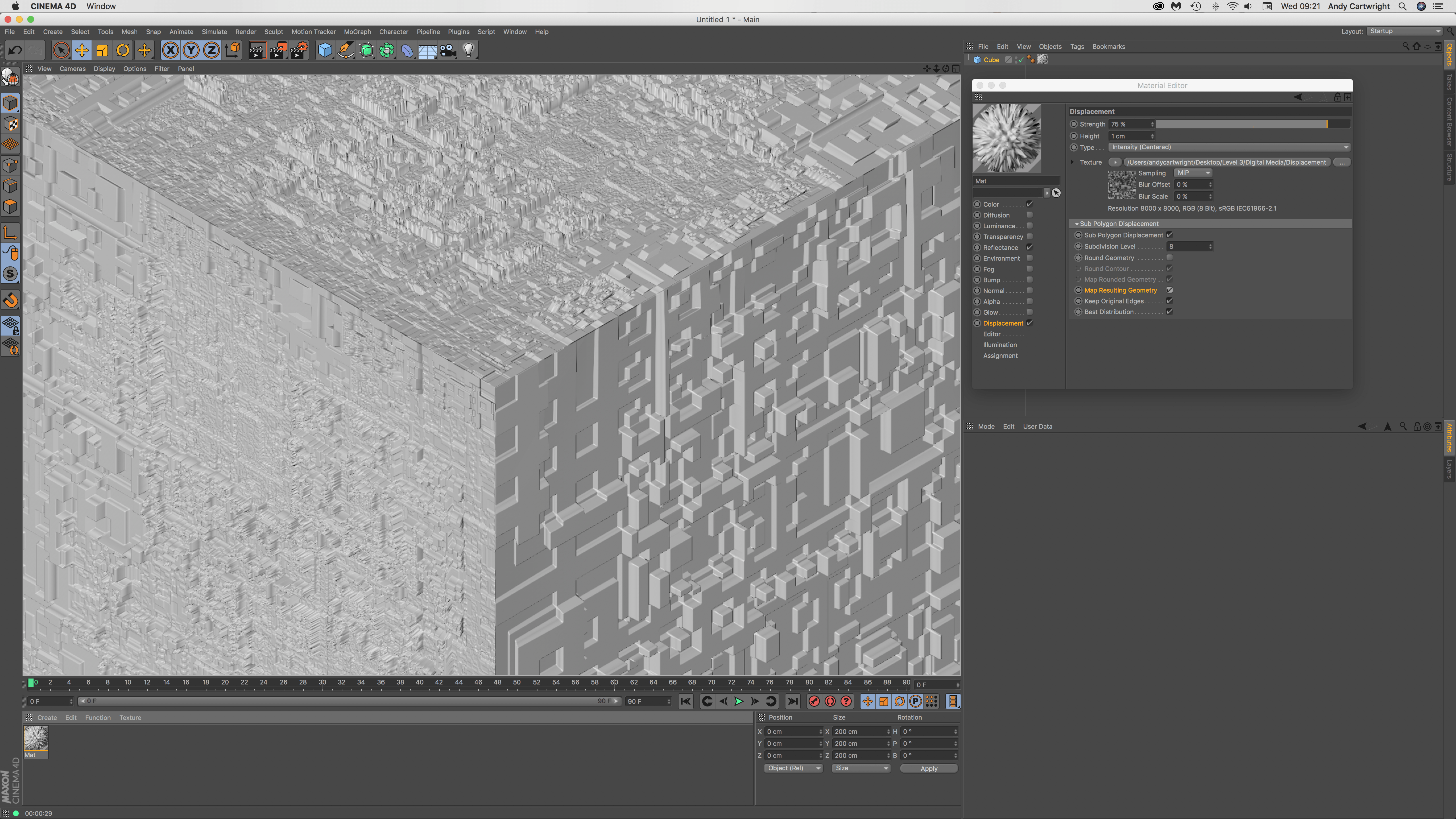
Even though the Mid-Level setting available in the Octane Renderer wouldn’t work for me, I still noticed that the node was connected the overall displacement material so I went an checked my displacement settings but nothing worked. So my next idea was to try an add a deformer, as I knew the object was a cube – I tried adding a bevel deformer to it to see if this would merge the vertices of the displacement map together, which I did but with an interesting effect.

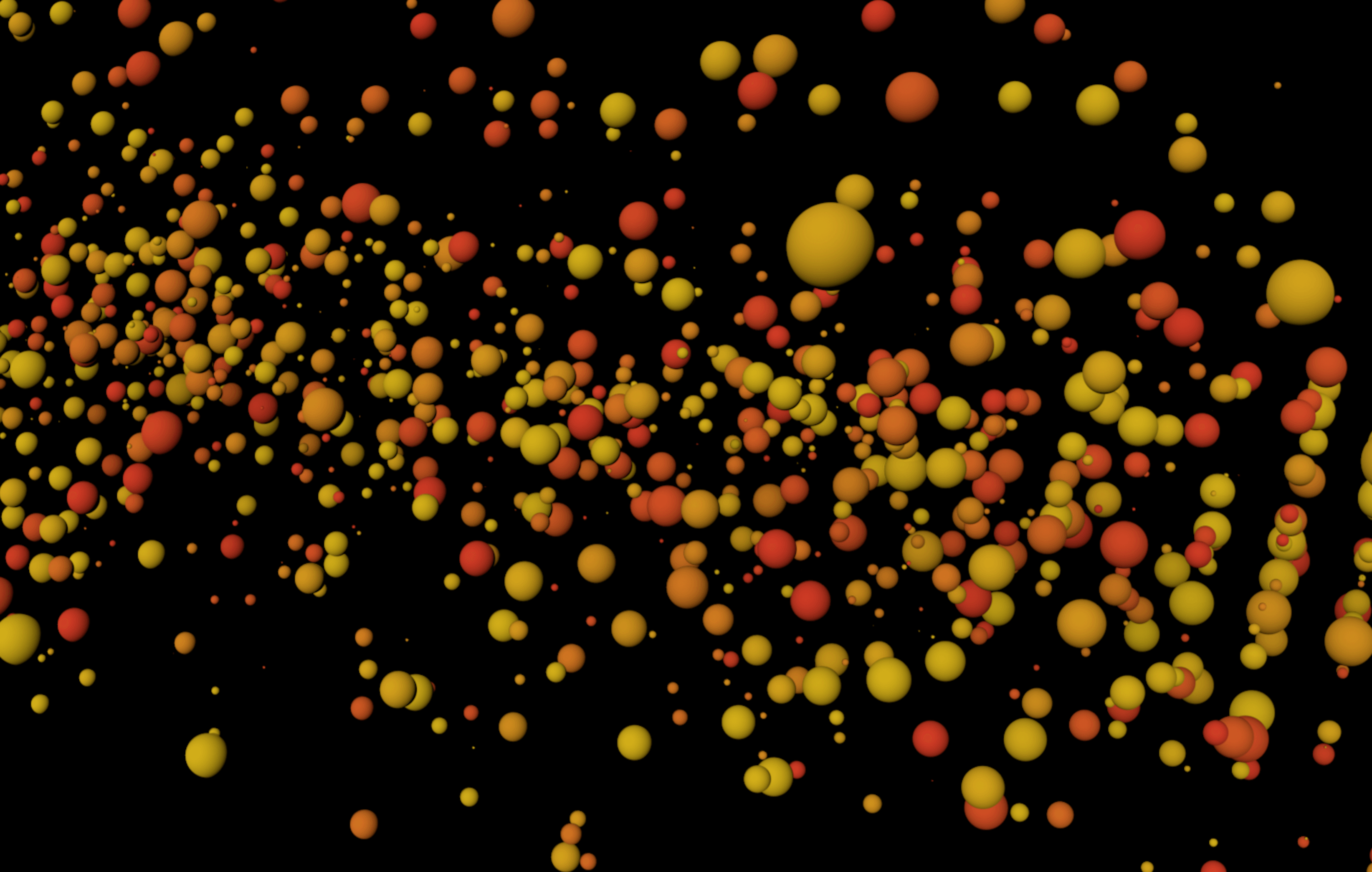
The effect can be seen below in the renders provided, the ‘before’ render shows that the object looked like before the bevel deformer was added to the cube – not how all the displaced shapes rise up quite high and there is a good amount of colour variation which was  achieved through the initial creation process.

Before:

Edgeissue


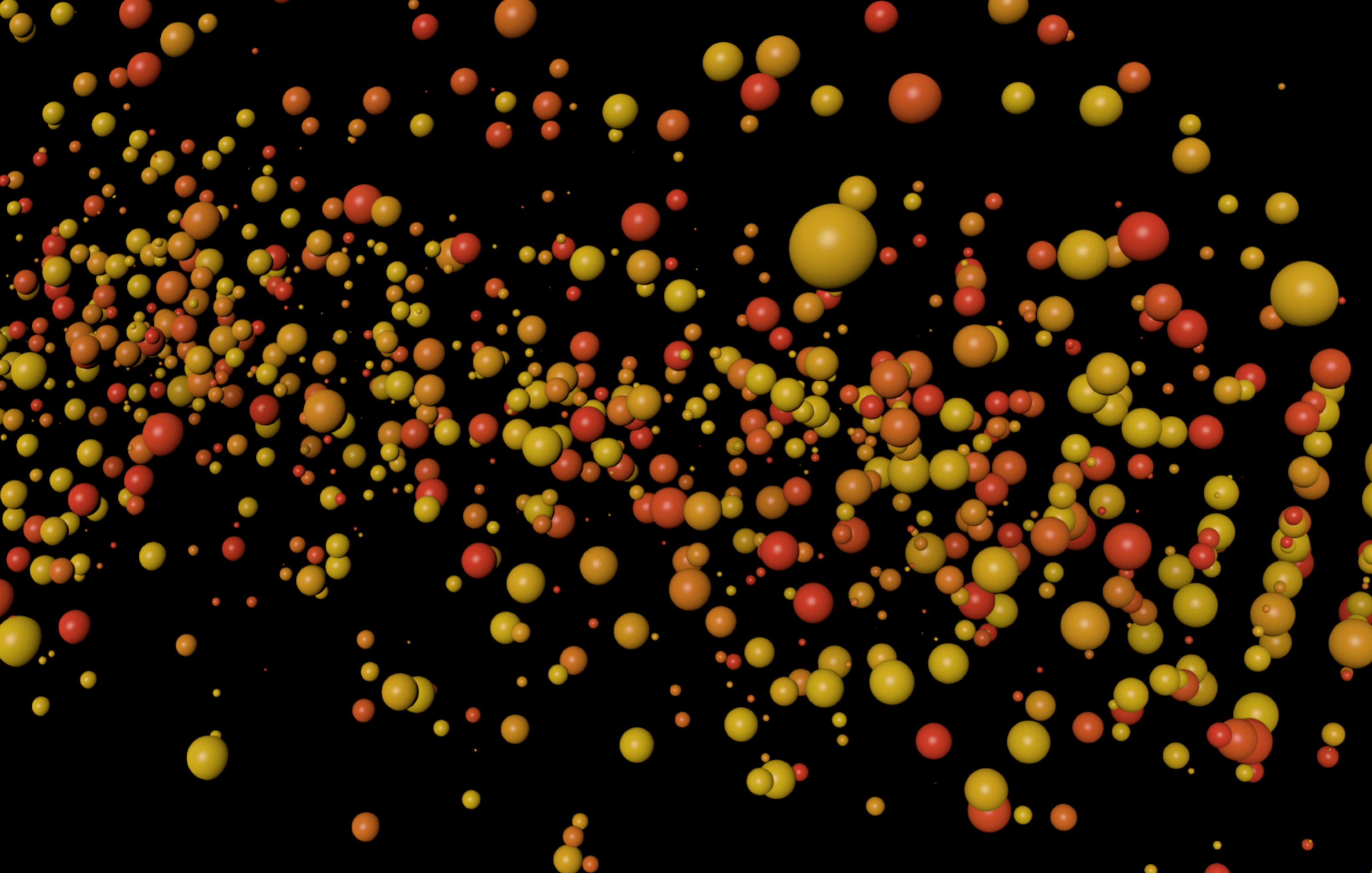
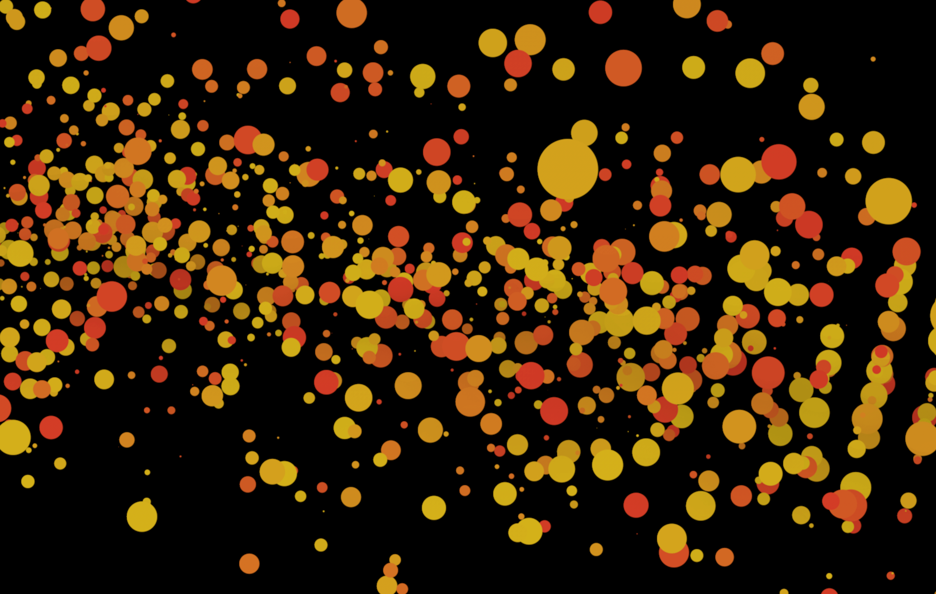
After the bevel deformer was added, it created an odd effect to the surface of the object by flattening the protrusions from the displacement map – also this result may have decreased the overall effect I was wanting to achieve, it also also solved the edge vertices problem that can be seen in the first render.

After:

Edgesoultuion

Overall, the bevel deformer has eliminated the holes in the displacement map on the vertices but, it has also changed the overall effect of the displacement map as the protrusions are lower in height and seems like the deformer has decreased the overall strength of the map. From a close perspective, I really like the effect the deformer has given the object as it resembles the surface of a space station or technologic material – however, I still need to the view the effect as a whole on the object as it might not look aesthetically pleasing form a distance. To further develop this I will continue to alter the settings of the bevel deformers to see what results they produce, which I will document with renders.

Displacement Map Problem

After successful adding the displacement map to the cube and adjusting the segments & sub-polygons, I noticed small section on the vertices of the cube where the map didn’t join up correctly – this can be more specifically be seen in the render below where square/rectangular holes are visible.

Edgeissue

As I intend to get some close-ups of the cube for the animation, this will need to be fixed. I think that this could either be done within C4D itself through the mapping settings on the material – the way the texture is mapped onto the shape is currently set to UVW Mapping which might have an involvement with the issue. In addition, it could also be done in  Illustrator or After Effects by adding a small white boarder to the edges above all the layers – this would mean that all of the boarders would be at the same displacement level as each colour density represents displacement value. I will research into this further and test any potential solutions.

Height Map Research & Testing

A continuation of the displacement creation inside of C4D, this time I tested a couple different ways in which I could make the map more defined on the cube as which I scrolled in the edges were slightly bevelled.  The video below shows my workflow:

Within this time-lapse video I was trying to tackle my problem with the displacement map – on certain areas of the map I experienced organic looking protrusions coming from the object and I didn’t know why it was happening. In addition, I also saw the some of the edges seemed very bevelled even when the segments were turned all the way up – soon after the software locked up and froze due to all of the RAM being used up on the computer. As this was either to do with the displacement map itself or the amount of segments on the object, I set about experimenting with all of the different settings.

Firstly, I tried to turn up/down the amount of segments within the cube itself to see if this had any effect. I found that the less number of segments the object had, the less flexibility the face of the cube had to deform to the displacement map, this often resulted in a less detailed map.

Secondly, I tried to alter the height and strength settings of the map but this didn’t really benefit the clarity of the protrusions in any way – When the height settings were increased, the physical length in which the protrusions came out to were increased as well and the this was the same for the strength setting too. Changing these settings at times did help occasionally, however, this wasn’t very beneficial as the whole aesthetic of the cube had changed to something I didn’t want.

Lastly, I tried to add Sub-Polygon Displacement to the cube which was under the displacement tab within the material editor. With this particular project I found that it drastically slowed down my computer and wouldn’t even allow me to render as it produced an error message: ‘Run out of application memory’ and prevented the scene to be rendered any further. I created another project file and loaded up the same displacement map (enabling the Sub-Polygon Displacement) and found that even with 1 segment for the X, Y & Z settings, the displacement map worked.

*Sub-Polygon Displacement – “In principle, sub-polygon displacement (referred to as SPD in the following text) is similar to displacement: an object is deformed during rendering based on a texture’s grayscale palette or, in some modes, color palette. The trick lies in the object’s own internal, adjustable and relatively high subdivision, which allows for very detailed structures without having to actually subdivide the object permanently. In many cases, it is impossible to achieve the same degree of detail through modeling because too much memory would be required.”

Sub-Polygon Displacement disabled

Screen Shot 2017-11-15 at 09.18.40

Sub-Polygon Displacement enabled

Screen Shot 2017-11-15 at 09.17.59

Map Resulting Geometry

Screen Shot 2017-11-15 at 09.21.09

All of the renders produced had 1 segment for the X, Y & Z settings – found that this was much faster to render with my computer and I also feel like the edges of each protrusion are less bevelled than before.

Conclusion

After experimenting with the sub-polygon displacement, I have come to the conclusion that the displacement map is far too detailed for what I need, meaning that there are too many fine details in the map that the displacement cannot displace – this is evident in the physical renders that are produced as you can see some of the shapes created in the map itself aren’t very geometric in shape and are more organic looking. To overcome this issue, I will create another displacement map that is more simplistic, this will allow for the displacement to produced protrusions which are more defined which could also be developed by experiment with colour in it. Additionally, Im looking at adding extra elements to the cube that might cover some of the sides – examples of this could be rectangular faces in the centre of the cube to add some diversity to the shape.

X-Particles Testing

After conducting research on X-particle materials, I set about re-creating my scene from before utilising the knowledge I had gained from watching the tutorial on youtube. I took a screen recording to show my workflow and I also experimented with trying to get the emitter object or the torus to rotate, this was to see if I could get the particles to rotate too.

Overall, the testing went well as I was able to produce something very similar to what I had envisioned and storyboarded. At the beginning, I made the x-particle system form a ring that stay relatively close together when particles were emitted from it – this was due to tweaking the xpSpeed settings and changing it to a negative value so that as the timeline continued to play, the particle speed slowed down. Additionally, I was able to colourise the particles with bright colours from a gradient that also had a glossy texture to them, I feel this element alone was good in comparison to the first test I conducted as the spheres seemed for 3D instead of just being flat objects. As well as the particle colour, I created an oversized sphere with a material added to it to create the background – within the test animation you can see faint white dots on the background which is apart of the texture called Starfield which is very convenient as it looks very attractive.

However, with the success of employing all my learned knowledge into the test, I wasn’t able to get the ring of spheres or the emitter to rotate. I feel like the solution to this might be very simple, however, due to having little exposure time to the software, Im probably just missing it.I will have to conduct some further research into this section and if unsuccessful, I think I will be able to get around this by panning the camera to create the same effect.

X-Particles Material Research & Testing

Here is another Youtube tutorial by Greyscalegorilla, the project being done doesn’t apply to my animation at all, however, there is a specific part which goes over x-particles materials in great detail which was very useful. The specific part in the tutorial starts at 15m 20s and ends at 19m 50s, which can be viewed below:

When experimenting with X-particles before in my X-Particles Research post, I didn’t know how to make glossy X-particle materials, specifically looking for a reflectance within the material.  When experimenting I came very close to discovering how to do this, however I didn’t select the right colour mode under: X-particles material > Illumination > Lighting > Mode. Under this section within the colour shader of the x-particles material, there are many different settings to choose from, each with their own unique effect which can be seen in the renders below – I feel overall the only one that I will use will be the Phong colour mode as it gives that glossy aesthetic to the material which I desire. However, it is key to note that there were other modes that also produced interesting features:

  • Diffuse – The diffuse mode is very much similar to phong as it brings a 3D effect to the particles emitted, it understands where the light is coming from within the scene and creates shadows accordingly to create the 3D illusion.
  • Fuzzy – The fuzzy mode is also very interesting as it blurs each of the particles making them seem more like dust or light splotches – I could see this being used within my animation to create a hazy atmosphere, however, the colours and opacity would have to be changed accordingly.
  • Neon –  The neon mode is by far the most different setting compared to all of the others – it adds a slight blur to each of the particles but also adds a strong luminance to each of them which can be seen in the background of the render. To me, I could see this being used to denote a blood vessel if a swatch of reds and dark pinks were used, the particles could also them be red blood cells or other cells found in the bloodstream.

Renders:

1) Diffuse

Screen Shot 2017-11-13 at 14.07.54

2) Phong

Screen Shot 2017-11-13 at 14.07.41

3) Flat

Screen Shot 2017-11-13 at 14.08.05

4) Fuzzy

Screen Shot 2017-11-13 at 14.08.15

5) Neon

Screen Shot 2017-11-13 at 14.06.57

6) Henyey-Greenstein

Screen Shot 2017-11-13 at 14.08.05

7) Schlick

Screen Shot 2017-11-13 at 14.08.05

8) Rayleigh

Screen Shot 2017-11-13 at 14.08.58